


JapanAxe
-
Posts
5,800 -
Joined
-
Last visited
Content Type
Profiles
Forums
Events
Shop
Articles
Everything posted by JapanAxe
-
Jazz Bass control circuits (passive) - what works for you?
JapanAxe replied to JapanAxe's topic in Bass Guitars
Well spotted! The bass came without the correct 6-32 intonation screw (actually a bolt). The original would be 1 7/16in (39mm) long. I sourced some 2in bolts and cut one a bit longer, as I suspected the original had been lost because it didn’t adequately engage with the bridge saddle. This topic is crying out for a PhD thesis! -
Jazz Bass control circuits (passive) - what works for you?
JapanAxe replied to JapanAxe's topic in Bass Guitars
What does the Turbo switch do? I’m kind of afraid to ask… -
Jazz Bass control circuits (passive) - what works for you?
JapanAxe replied to JapanAxe's topic in Bass Guitars
Yes that may be the way to go. I keep having to remind myself that this bass is basically a MIM Roadworn with some extra relic’ing, not a vintage instrument! A couple of Christmases ago I woke at 4am, and was still awake at 5am, so I got up and (with the help of a YT video) replaced the heater roller in my laser printer. That put me in a good mood for the rest of the day. In the meantime I’ve had another idea… -
Jazz Bass control circuits (passive) - what works for you?
JapanAxe replied to JapanAxe's topic in Bass Guitars
I decided it would be good to keep at least some of the stack-knob look by turning one volume/tone pair into master controls, and replacing the other with a rotary pickup selector or blender, using just the chromed volume knob. But can I hell get the volume knobs off? It feels like the screws have been tightened with one of those air tools that tyre fitters use. I have tried WD40 and heating the knob with a soldering iron, so far without success. The grub screws are slot-head types, and as I apply more torque the screwdriver blade starts to distort, or the blade cams out of the slot - you can only do that so many times before the screw is mullered. Any tips folks? And if you're wondering why I'm sat doing this on Christmas Eve, we've just had tea with the grandkids, and Mrs JapanAxe has sent me to my music room while she does some last-minute wrapping! -
Exactly what I was going to recommend. I recently put one on my main lead guitar pedalboard to mix in wet-only signals from two delay pedals. It works a treat and was stupidly inexpensive - less than £50 on Amazon, even cheaper on eBay. It’s a clone of the discontinued OBNE Signal Blender.
-
Jazz Bass control circuits (passive) - what works for you?
JapanAxe replied to JapanAxe's topic in Bass Guitars
I’ve never hankered after the series option, in fact I rarely use it on my Dingwall NG2. I’d be interested to see how the two volume controls interact in series mode. -
Jazz Bass control circuits (passive) - what works for you?
JapanAxe replied to JapanAxe's topic in Bass Guitars
With this circuit, centre position on the blend control means both pickups are connected direct to the master volume and tone controls, so that would be equivalent to both volumes maxed in a VVT setup as you say, needed to reject RF interference. Neck full / bridge 20% should also be achievable. -
Jazz Bass control circuits (passive) - what works for you?
JapanAxe replied to JapanAxe's topic in Bass Guitars
I've just finished reading most of the 18-page Talkbass thread, which runs from 2014 to August 2025! I'm going to go for a 100k MN blend pot and cut the traces for full isolation at the extremes, so I've ordered a pack of 5 via eBay. If I don't like it, I've found there's room in the cavity to fit a rotary selector switch. -
Jazz Bass control circuits (passive) - what works for you?
JapanAxe replied to JapanAxe's topic in Bass Guitars
My stack-knob Jazz is definitely bright compared to my Precisions, but I enjoy the contrast. -
Jazz Bass control circuits (passive) - what works for you?
JapanAxe replied to JapanAxe's topic in Bass Guitars
I’m on board with ‘simple’ but I do like to ride the tone control from song to song. -
Jazz Bass control circuits (passive) - what works for you?
JapanAxe replied to JapanAxe's topic in Bass Guitars
Just because you could do something doesn’t mean you should! -
I recently acquired a lovely Jazz (having sworn off them for a good few years) and I find myself facing the same first-world problem that I always have - quick changes to the sound. I know that many people swear by the Volume/Volume/Tone (VVT) setup, and like to juggle the volume controls for subtle changes. Frankly I find these too subtle to be worth bothering with, and I converted my last Jazz to Volume/3-way switch/Tone, a bit like a lot of the passive Yamaha BBs. My current Jazz is a stack-knob with the later variant control circuit (no mixing resistors) and I'm starting to think a little modding might be in order. The everything-on setting alone is worth the price of admission but I have the same issue as with the VVT in that there is only any tonal change over about 1/10 of a turn of either volume knob. It has 250k volume pots but 500k tone pots, so very little happens to the tone until the bottom quarter of the pot rotation. For now I have tacked a couple of 56nF resistors in parallel with the existing 50nF ones, which has improved things from my point of view. I'm currently considering getting a 3-knob control plate and setting it up in one of the following ways: Vol/3-way/Tone Vol/Blend/Tone as per the diagram below - I originally found it on Talkbass but then found that @TRBboy had posted this thread about it last year. I could easily try both and see which I liked best of course So - what passive blends have members had success (or not) with, and who gave up and either fitted a 3-way switch, or returned the bass to stock?
-
I play guitar in a rockabilly band where the double bass player wraps sticking plaster around each of his plucking fingers before playing. I don’t play double bass so I’ll leave it to others to comment on the pros and cons of this approach!
-
No, it’s never occurred to me to think like that! I decide which bass I think will work best for the gig and take that, and sometimes a spare.
-
I currently have ongoing involvement with the following, in no particular order: - Bowie tribute 7pc - 2nd guitar (member) - gig booked in January, more in 2026 subject to confirmation - Rockabilly/country/originals 4pc - lead guitar (member) - gigs in 2026, BL actively seeking quality work including R’n’R festivals - Glam covers startup 4pc - lead guitar & MD (member) - showreel completed, BL now looking to launch us into theatres - Dire Straits tribute 6pc - rhythm guitar or bass (dep) - played about 10% of their 2025 gigs, more booked for 2026 - Pub covers band 4pc - lead guitar (dep) - covered for long-term illness but they have a new guitarist for 2026 - Rock’n’roll band 4pc - guitar or bass (dep) as required - nothing in the pipeline with them but they just call me if they’re stuck - Swing band 17pc - bass (or potentially guitar) (dep) - I cover their Monday night rehearsal if the regular guy can’t make it - Prog/pop covers band 5pc - bass (dep) - one member quite well known in the YouTube guitar scene - saw them, loved the set, familiarised myself with the set, dropped shameless hints to the keys player who I know, ended up covering 2 of their rehearsals Also-rans from 2025: - One-off jazz and jazz-adjacent gig on guitar, with the keys player mentioned above and a female vocalist, at a charity fundraiser that was a logistical nightmare - Asked to dep on bass for a theatre gig with a classic rock covers 6pc, suggestion of more opportunities next year - got well into learning the set but then the gig got pulled and I suspect the band is no more (website has gone) - Not long after that gig got cancelled, I got a request to stand in on bass with a blues band for the same night, which of course I did! EDIT: Forgot a dep gig on bass with a 4pc country band!
-
Yep. keep it short and to the point - a minute is plenty! I couldn't get to them before when I was on my phone, but here are a couple of shots from the stalls taken by the singer's husband. I'm stage left, playing the red Tele. The videographer also used a drone to get shots from angles that couldn't otherwise be achieved. The whole thing cost us about £400 at mates' rates, but if you are paying full professional price you will be lucky to get much change from a grand.
-
A band I am rehearsing with recently made a showreel. The BL has his sights set on theatres, for which you need something that an agent can send to a venue. First we made multi-track recordings of a couple of rehearsals, and I edited together acceptable (but not perfect) versions of the 6 songs we’d chosen. It helped a lot that the drummer plays an electronic kit! We then hired a small theatre and a videographer came along and filmed us miming to our live-in-the-studio recordings. We got mates’ rates because the BL knows him and he is trying to break into band showreels. Afterwards the videographer edited together a draft and there then ensued considerable back-and-forth over what did or didn’t work. I think it’s finished now and will be launched in the New Year.
-
NBD was actually Sunday, but I won't tell if you don't. I've been a dyed-in-the-wool Precision devotee for quite a few years, having found that they just work for me. But slowly the worm has turned... My Dingwall journey led me along the path Super P > D-Roc > NG-2, which obviously opened up non-P possibilities. I tried a friend's Jazz (American Standard?) and thought, 'I like this!' Then I found a 2001 MIM J at an auction, loved it, but was outbid. I was pretty disappointed. Finally I came across this Flea Jazz being sold by our own @Mickeyboro, tried it, loved it, brought it home, loved it even more. If I'd been a good boy I'd have shifted my D-Roc first, but clearly I'm not - no presents for me, but that's fine, I'll just sit and play this. It does what I hoped a Jazz would do - a different and spankier voice but still with authority behind the notes, a comfortable playing experience, and a sound that makes you think, 'Ooh, that's like a record I've heard'. Going between this and my original '73 Precision, the Flea Jazz feels old like the '73, not least because it has nicely rolled fingerboard edges. I've spent some time tweaking it to my preferences - neck relief, action, Monty's Instrument Food, and a replaced intonation screw (disclosed prior to purchase) and have been having altogether too much fun going through my Steely Dan transcriptions. I'm not sure when I'll get the chance to gig it, but there may well be a 70s covers rehearsal in January, for which this would work a treat!
- 4 replies
-
- 20
-

-

-
Just bought a lovely Jazz bass from Mick - second attempt at a try-out after I suffered a serious attack of the Running Snots. Mick is a proper gent, and we could easily have whiled away the entire afternoon chatting!
-
You can download the app for free. Then you need the extension (or whatever it's called) for the mixer you're using. If it's the Behringer XR18 you'll need the one called 'X/M Air' - it's free on Android and just a few quid on iPhone. This video may help:
-
Do you have full control over your own monitor mix, eg via a phone app? My IEM experience was initially poor and hugely variable until I did.
-
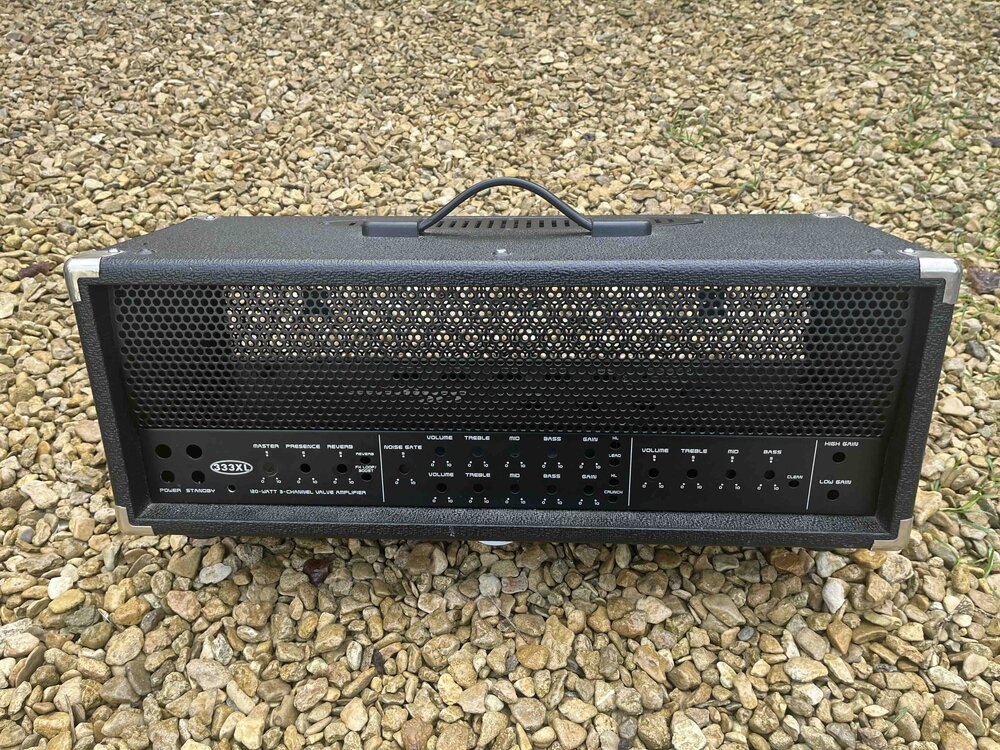 ** NOT A COMPLETE AMP - JUST AN EMPTY HEAD SHELL AND CHASSIS ** ** SPARES/DIY ONLY ** This is what remains of the amp that I gutted for my 100W bass amp build. It has one non-matching 30mm M4 bolt and the Bugera logo is missing, otherwise all good. Too big and heavy to make postage worthwhile so £25 collected or meet-up. I live in Swindon but do travel round for gigs and so on.
 -
Only £1,150 for this stellar Tele!
-
 Multi-pedal bump.
 -
Slow market innit!


