


JackLondon
-
Posts
586 -
Joined
-
Last visited
Content Type
Profiles
Forums
Events
Shop
Articles
Posts posted by JackLondon
-
-
Mine was,
Hohner P-Bass copy, worth about £60 12 years ago, put me off having anything shaped like a p or j bass for life.
Laboga 15W amp worth about £30 12 years ago, it had a single 10" and farted out at about half of the volume, I've played for 4 years on it.
A strap, gig bag and a cable thrown in for free with the bass, I still use the strap even today, everything else is gone. -
price drop bump
-
[quote name='s1ater' post='807495' date='Apr 15 2010, 07:01 PM']Fair enough, cant blame a guy for trying
 [/quote]
You must try harder son
-
[quote name='s1ater' post='807456' date='Apr 15 2010, 06:20 PM']I really fancy one of these, but Ive blown all my money on an m pulse 600 and new studio stuff

Dont fancy taking £250 for it do ya?[/quote]
To be polite, No
-
-
-
-
[quote name='umph' post='801200' date='Apr 9 2010, 08:12 PM']output from switch is going to the ground tag on the output jack.
Personally i'd recomend redoing the wiring, remember the shorter the better it'll kill most of the noise to.[/quote]
I've done that, thanks for the tip
[quote name='LukeFRC' post='804388' date='Apr 12 2010, 11:23 PM']make an audio probe and follow the sound through. I recomend some kinda cheap amp to do this too as there will be a lot of popping.
Now i stress i dont know what i'm actually looking at but looking at the schematic i would guess you are getting the signal through R12.
I would then test each bit of the circuit, i.e. pin 12 of IC1, then pin 1 of the threshold pot and go through the whole thing methodically. I personally would also bypass the mods you've stuck on like the switch between G and H just to rule that out.
I had a tonepad board for the chorus and there was a wee break that it took me ages to find.[/quote]
I did follow the signal through with a probe and it goes everywhere, the problem is there's no wah sound. I've taken off all the mods and taken the circuit out and wired it directly to jacks without a switch, my voltages are getting close to where they should be but there's still nothing happening. -
-
[quote name='Al Heeley' post='803349' date='Apr 12 2010, 07:48 AM']Thats very neat work there! Have you traced the signal path all the way thru with an audio probe? Have u double-checked you have the IC's in the right way round?
any replacement ones you can slot in and try? what is the 8-leg one, a standard op-amp chip?[/quote]
Yeah I've checked the IC 1&2 and they are correct, the 8 pin one is TL072. Where the first problem was is 5V reg that I put wrong way around, I have some new IC on tye way because I think IC1 is fried. We'll see when it comes. -
I take the following :
12 x Leads, 4 Primary and 4 spare plus 4 spares for spares
2 x 4-way extension, that's just in case the one on the back of my rack fails
2 x power supply for my Boss, 1 primary and 1 spare
2 x power leads for the amp, 1 primary and 1 spare
3 x cable speakers, 1 primary and 2 spares
2 x set of strings Dr Lo-Rider strings
2 x Strap, 1 primary and 1 spare
3 x 9v baterries, 1 primary and 2 spares
Screwdriver, allen keys, vice grips, cable cutters, cable ties, small torch,
You can never be ready for everything but I never had a situation for which I didn't had a backup. -
Another pedal that doesn't work, this time Rebote 2 Delay, no clue where it all goes wrong with pedals htat have IC's in them

Also as suggested by umph (cheers for that) I reduced the amount of wiring inside the box so it all looks more neat and tidy, but still doesn't work
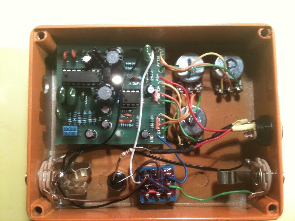
Any ideas where to start ? The signal goes through the circuit but it's not delayed, so reports from other forums suggest that the delay happens at pin 15 of IC1 but it doesn't in mine. there's no delay at all. -
-
[quote name='gelfin' post='802213' date='Apr 10 2010, 10:54 PM']Hi you may want to check out this company.
[url="http://www.chord.co.uk"]http://www.chord.co.uk[/url]
They mainly make Hi end cables for Hi Fi but a lot of them play in bands and are passionate about music.
The Chord "Cream" is their instrument cable, I use it and love it.
Here's a direct link to their instrument cable page.
[url="http://www.shopatron.com/home/search/1390.0.4.3?q=cream&x=0&y=0"]http://www.shopatron.com/home/search/1390....amp;x=0&y=0[/url][/quote]
Now point me to the difference between those cables and OBBM apart of being 4 times more expensive ? -
so I don't break any rules, you have a PM
-
Looks like it will stay with you forever!
-
-
I've already redone the wiring, that was why it wasn't working in bypass, now it works but doesn't wah.
-
Right I had enough if this bugger. Anyone can fix it for me? Willing to pay!
-
Price drop bump
-
Right, managed to get it sort of working, I've changed the 4066IC and it now has a signal going through the circuit (a bit lower in volume than bypass) but it's not doing any wah wahing. When turning pots there's sometimes a sort of high pitch hiss constantly and when the emphasis pot is fully turned it has a sort of popping sound when nothing is played...don't even know where to start looking...
-
Hi All,
Yeah I posted in on diystompboxes.com and so far they've told me to check off board wiring which I did and it seems fine to me,
here's the schematic for wiring I've followed :
[attachment=46805:wiring.jpg]
This is the picture of the box :
[attachment=46806:IMG_0204.JPG]
There can't be any problems with shorts as the circuits sits on 2 standoffs and a bit of foam, there's signal on C4 and R1 but's it's so quiet that it is almost impossible to hear.
I'm now thinking about the IC's as someone said that pin 7 should be 0V and pin 14 should at least a couple of V, having read the build reports on tonepad I think that my IC's are the ones that are reported as non-working in this circuit.
-
Guys, HELLLLPPPP
I've got a problem with one of the circuits, here's the spec as per diystompboxes.
1.What does it do, not do, and sound like? – Doesn’t put enough signal to the output, it’s very very very silent. In bypass mode there is no signal at all.
2.Name of the circuit = Agua Filter
3.Source of the circuit (URL of schematic or project) = [url="http://www.tonepad.com/project.asp?id=4"]http://www.tonepad.com/project.asp?id=4[/url]
4.Any modifications to the circuit? – Yes, Emphasis control, reverse sweep, filter range, all from the schematic
5.Any parts substitutions - No.
6.Positive ground to negative ground conversion - No
7.Voltage at the circuit board end of the red battery lead = 9.11
Voltage at the circuit board end of the black battery lead = 0.79
IC1
P1 0.34
P2 0.19
P3 0.20
P4 0.18
P5 0.14
P6 0
P7 0.79
P8 0.20
P9 0.21
P10 0.20
P11 0.21
P12 0.22
P13 0.74
P14 0.17
IC2
P1 0.56
P2 0.21
P3 0.21
P4 0.21
P5 0.70
P6 0.24
P7 0.79
P8 0.71
P9 0.23
P10 0.20
P11 0.23
P12 0.23
P13 0.75
P14 0.17
IC3
P1 0.66
P2 0.69
P3 0.70
P4 0.68
P5 0.73
P6 0.71
P7 0.79
P8 0.14
P9 0.00
P10 0.14
P11 0.47
P12 0.71
P13 0.74
P14 0.17
D1
A = 0.04
K = 0.17
D2
A = 0.10
K = 0.15
Cheers for any help
Jack -
Band Members wanting to alter the 'look' of your gear.
in General Discussion
Posted
Wouldn't consider changing the grill unless the leader paid for it, if not the tell him to f*ck off and get one of those :
[attachment=47688:jazz_cafe.jpg]
It cost us £100 and it can be hang everywhere, also what about the times you would play on someone's backline or venues equipment ?