


3below
-
Posts
2,695 -
Joined
-
Last visited
Content Type
Profiles
Forums
Events
Shop
Articles
Everything posted by 3below
-
My first tactic would be purchase a sanding detail stick (aka fret dressing / crowning stick £5 tops), masking tape or fret protector strip and a short length of straight metal (you can purchase a fret rocker if you want). Remove strings, adjust neck to flat and crown frets spending a bit more time on any that are 'high'. It is unlikely that there will be any major issues on a bass of this quality. Put strings back on and adjust truss rod, saddles and neck shim if needed (there are many good setup guides on youtube). It really is an easy DIY job and with a sanding detail stick you can not do any significant damage. If this does not work then Grangur's advice is on the money. At that point it is a matter of cost - benefit - how much do you like the bass (unless you can diy level and recrown).
-
Finished! And now for something completely different ...
3below replied to Andyjr1515's topic in Build Diaries
It will be 'interesting' getting the finish inside the curves. I look forward to finding out how it should be done -
Am thinking that the issue was how much wood was left above the wing cut outs etc. The answer is above from Beedster. As for DIY bridge adjustment it depends on how much your action needs lowering. Three to four mm I would go for it DIY personally. With my DB I spent £12 on a replacement bridge (Chinese maple) and fettled it based on the original one (my original bridge was 'buckling' and increasingly of no use).
-
Best advice is wait until one appears for sale on BC. Not that long ago one appeared on an Epi EB bass here for very sensible money, they do appear regularly. With the supertone, the allen screws that lock the saddles laterally can present sharp edges to your palm. Fit them from underneath and the problem goes away.
-
[quote name='Andyjr1515' timestamp='1478378054' post='3168776'] That's looking really nice [/quote] Thank you Thinking about finishes, which you did reply to previously on your EB3 type build. I am aiming for brown (like your LP Junior) - Chestnut brown mahogany spirit dye?
-
[quote name='scrumpymike' timestamp='1478371565' post='3168735'] Well done! IMHO W machine-head alignment suits headstock design. [/quote] Thank you, I could run a BC poll lol
-
Slightly better pictures
-
Fair progress with good technique today. Only one design blunder that I would do differently next time. Tried 3 times with this photo, poor quality image Neck pocket is super fit, better than anything USA made that I currently own Time well spent on constructing template and much improved router skills. I pondered leaving the pocket in old Fender style, i.e. loosen neck to access truss rod. Decided not to, ho hum hence the design error, truss rod adjusting rout way too big for what is required. Looking like a bass now. design error now stylishly covered, totally intentional. Laminations, set square and careful centre line measurement get the machine heads in line. Extra care taken with drilling following Andy's helpful lead in this aspect Choices now, traditional machine head layout or W style? Finally the moment of truth, string alignment with bridge. Have my measurements, centre line and 'skill' produced something that aligns correctly? Amazingly the answer is yes
-
 I paid for this in full on the 2nd of October, it still has not arrived and you are selling it again. Disappointing.
 -
This chancer is so far adrift of the ethos and spirit of BC.
-
Finished! And now for something completely different ...
3below replied to Andyjr1515's topic in Build Diaries
Are the black lines in the body finish or actual 'cuts' through the body ? -
[size=4]The following also aids you considerably. Fourteen days from receipt of good to reject.[/size] [color=#05171D][font=OpenSans-Regular,]The Consumer Contracts (Information, Cancellation and Additional Charges) Regulations 2013 require traders to give you certain information.[/font][/color][color=#05171D][font=OpenSans-Regular,]The Regulations came into force on 13 June 2014 and apply to contracts entered into on or after that date.[/font][/color][font=OpenSans-Regular,][size=5] [size=4]Look here [url="http://www.which.co.uk/consumer-rights/regulation/consumer-contracts-regulations"]http://www.which.co.uk/consumer-rights/regulation/consumer-contracts-regulations[/url][/size][/size][/font]
-
I use the very same strings on several short scale basses. Particularly impressive (to my ears) on my SG bass.
-
Anyone know of any 'defretter' effects out there?
3below replied to AinsleyWalker's topic in Effects
[quote name='Grangur' timestamp='1477861137' post='3164926'] Here's [url="http://www.tonetechluthiersupplies.co.uk/summit-ergonomic-fret-cutter.html"]a link[/url] to the best on the market [/quote] Surely this: £24.99 bargain, however I have found it leaves marks on the fingerboard if you are not careful. In all seriousness it is surprising that the 'defret' pedal does not exist. -
How DIY are you? Self build e.g. steel frame, timber cladding could reduce costs considerably. If you are using a concrete slab floor I would strongly suggest getting it made to current building regs standards with insulation. The difference with a fully insulated building is quite staggering - I do not need to use the heating in my south facing 'hutch'.
-
Shortscale and sparkly. On a budget. By a Beginner
3below replied to FuNkShUi's topic in Build Diaries
Before undertaking wholesale stripping, try some paint stripper under the pickguard, see what happens. I have a body that was so resistant to paint stripper and the heat gun that I gave up. Another possibility would be to key the existing finish and spray onto that. Again try in an inconspicuous spot first just in case that the paint reacts. Others who have much more experience will be along soon -
Onwards progress and another unforced error Body sides routed to template using the 2" down spiral bit (a 'serious' cutter). Only one small tear out (my fault whilst waiting for the router to spin down ). I was able to lose it with a bit of judicious template adjustment. Round over on the top went well apart from some cutter scorch marks. Will try slower router speed next time however I have had this problem with Oak before even at slowest speed. Round Over on the back went well until I forgot to stop at the jack socket hole (which I had thought about and planned to hand profile similar to where the binding ends on the unmentionable 4001 bass). Needless to say the roundover bit wandered into the hole. Repair section let in which should hide reasonably well when I stain the body 'dark brown'. Body now sanded to 180, sides all level with router ripples removed. Time to get my new toy out, Veritas cabinet scraper and remove the planer - thicknesser ripples. So many things I will do differently on the next incarnation.
-
The bar has been set high
-
Another small step, self explanatory. Home made bobbin clamps worked well. Yet another silly error I had remembered that I must put a drawstring in to ease later wiring. Got the string and sorted to fit etc. Proceeded to glue top on and noticed I had not put the string in. Marks on the oak top are just water from sponge used to clean up glue squeeze-out.
-
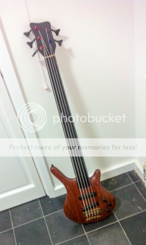 Gorgeous looking bass. As a Warwick owner if you had not said otherwise I would have thought Warwick. String spacing at bridge may help with sale, some of us can not deal with 'narrow' spacing some can.
 -
NBD: Warwick Corvette 5 string: Refin in progress
3below replied to Grangur's topic in Repairs and Technical
Super job and so satisfying to be able to DIY (in this case not destroy it yourself ) -
[quote name='samhay' timestamp='1477212786' post='3160519'] High pass and low pass are easy - you only need a resistor and capacitor. For high pass, put a capacitor between the pickup and volume pot (i.e. in series with the pickup). If you are using a 500k volume pot, then try cap values of about 2.2n (0.002). Bigger values give more bass/lower corner frequency and vice versa. [/quote] Following on from this, combining the two filter types will give a notch just using RC if you want. [url="http://www.learningaboutelectronics.com/Articles/Notch-filter-calculator.php"]http://www.learningaboutelectronics.com/Articles/Notch-filter-calculator.php[/url] (this is just the first site I stumbled across). Too much choice, too little time left
-
[quote name='White Cloud' timestamp='1477124370' post='3159954'] Electronics, mweh....a necessary distraction from wood loveliness [/quote] Occupies the time while glue is setting, varnish is drying or I am too tired and will make irreparable mistakes in wood. samhay and Andjr, thank you for providing insight, advice and encouragement for problems that I can not let go of. Spurred on by samhay I have spent some time playing with QUCS circuit simulation (which uses ngSPICE) and the original diagram Andyjr started with. Diagrams and data to follow, but the broad picture is that the early circuit is a high pass filter. Having owned a 58 EB2 many years ago this is exactly what the 'baritone' switch did - removed some 'muddiness'. What is interesting is the effect of the inductance of the 'mudbucker'. Although I measured the voltage output iof my EB2 at 1.5V ish E string (Sixth form Physics) The modelled values give an output voltage way below this. I did not measure the inductance of my EB2 nor have I found the inductance on the internet either. More thinking, modelling and some diagrams to follow. I need to find the inductance of the DiMarzio as well.
-
Samhay, thank you. Looking at your model you have LCR in series (which makes sense as a 'notch' filter). From my several trace throughs and redraws of the EB3 mk1 filter circuit I end up with pickup output into the parallel RC network in series with L to ground. The output to jack tip is taken from the node between RC and L. I am still on the learning curve of understanding what it does. The mk 1 circuit is where Andyjr started from which is why I am following it through (and pure curiosity and reminding myself of what I used to be able to do a long time ago).
-
The inductor has some 'mystery' with the published figures. Allegedly a wrong value was published to lead competition astray.. I would go with the 1.5H that Andy has. What software are you modelling with? Thanks